Physical Setup - Gateways & Cards
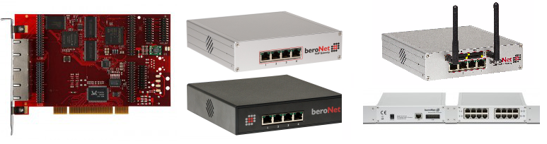
VoIP PCIe Cards
beroNet VoIP PCIe Cards are OS independent and can be used with Linux, Unix, Windows and MacOS. This technology incorporates a proprietary beroNet OS which is automatically detected by your system as a network card. Therefore all necessary drivers are automatically loaded by the OS of the host machine.
The PCIe Card is connected via PCIe and needs one 12V 4-Pin male Molex connector for power when used with specific modules (more information below). Network connection is handled through the PCIe and the host system and the card will get its own IP-Address in the network.
beroNet VoIP Cards have two module slots, with the first slot controlling ports one and two and the second slot controlling ports three and four.
Depending on the modules you are using, different slots with different pin-outs are used. This will be described in the modules section.
beroNet VoIP Cards are available in three different models:
| Models | G.711 Channels | Codec Translation | T.38 Channels |
|---|---|---|---|
| bf400e | 16 | 4 | 4 |
| bf1600e | 64 | 16 | 16 |
| bf6400e | 120 | 64 | 32 |
PLEASE NOTE: A beroNet VoIP Gateway Card CANNOT be transformed into a "Box-version"!
Modular VoIP Gateways
beroNet Modular VoIP Gateways are similar to the beroNet VoIP Cards. These devices include a NIC - RJ45 port and a 12 V power module and are enclosed an an aluminum chassis.
PLEASE NOTE: A beroNet VoIP Gateway (Box - Chassis) CANNOT be installed in a PC!
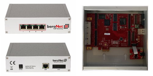
All features that apply to the VoIP card also apply to the modular VoIP Gateways.
| Models | G.711 Channels | Codec Translation | T.38 Channels |
|---|---|---|---|
| BF400 | 16 | 4 | 4 |
| BF1600 | 64 | 16 | 16 |
| BF6400 | 120 | 64 | 32 |
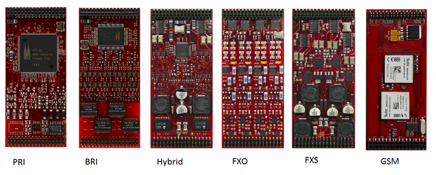
Modules
There are 10 different modules available for beroNet VoIP products:
- Hybrid: 2BRI + 2FXS (2HYB)
- Analog: 4FXS / 8FXS / 4FXO
- Mobile: 2GSM
ISDN (high precision +- 2.5PPM): 4BRI / 2PRI (E1/T1) / 1PRI (E1/T1) / 1E1 / 2E1
Starting in 2021, the 1E1 and 2E1 modules are also equipped with a high precision clock for DECT
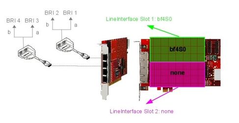
BNMO-4BRI (4x BRI/ISDN)
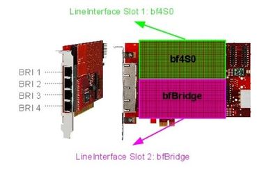
The BNMO-4BRI module has 4 ISDN/BRI ports. The 4BRI module can be configured individually for each port to NT (Network Termination) or TE (Terminal Equipment) mode. In either mode, the module supports Point-To-Multi-Point (PMP) or Point-To-Point (PTP). The TE/NT mode as well as the line-termination of 100 OHMs are selectable via software (Jumper Free).
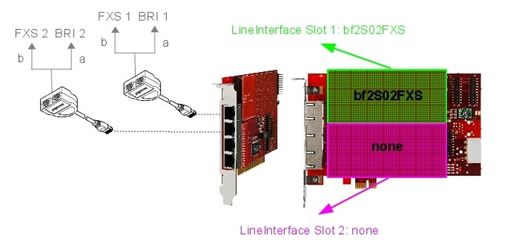
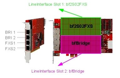
Depending on which line interface socket you plug the 4BRI module, the pinout is different. To best fit your needs, the use of the BFBridge is recommended instead of the BFTAdapters as seen in the picture below.
The following examples give you an overview about it: PinOut port 1 and 2 of BF4S0 module through Jack 1
| Port 1 | Port 2 | ||
|---|---|---|---|
| PIN | Usage | PIN | Usage |
| 3 | TX+ | 1 | TX+ |
| 4 | RX+ | 2 | RX+ |
| 5 | RX- | 7 | RX- |
| 6 | TX- | 8 | TX- |
Port 3 and 4 are similar to the above mentioned scheme only they use Jack 2.
| Line interface 0: BNMO-4BRI | Line interface 0: BNMO-4BRI |
| Line interface 1: none / empty | Line interface 1: BFBridge |
|
|
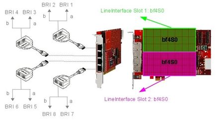
| Line interface 0: BNMO-4BRI |
| Line interface 1: BNMO-4BRI |
|
BNMO-xPRI and BNMO-xE1 (1,2 ports ISDN PRI)
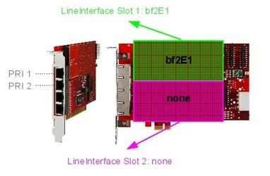
The BNMO-xPRI modules are available as 1 port or as 2 port variants. The modules can be configured individually for each port to NT (Network Termination) or TE (Terminal Equipment) mode. If you want to use NT-mode you may need a cross cable which is optionally available (BNE1Cross). Line termination (120 ohm) is selectable for each port by DIP switches on the module(2 per port).
The BNMO-xPRI have are equipped with a high precision clock with +- 2.5ppm.
Starting in 2021, the 1E1 and 2E1 modules are also equipped with a high precision clock.
| Port 1 | Port 2 | ||
|---|---|---|---|
| PIN | Usage | PIN | Usage |
| 1 | RX- | 1 | RX- |
| 2 | RX+ | 2 | RX+ |
| 4 | TX- | 4 | TX- |
| 5 | TX+ | 5 | TX+ |
The following examples will show you the different combinations of the module:
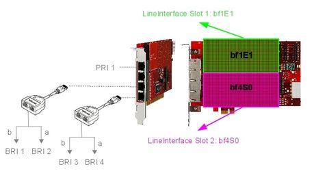
| Lineinterfacesocket 0: BNMO-2E1 | Lineinterfacesocket 0: BNMO-1E1 |
| Lineinterfacesocket 1: none | Lineinterfacesocket 1: BNMO-4BRI |
|
|
BNMO-4FXS (4 ports analog FXS)
The BNMO-4FXS module is a 4 port FXS module for the beroFix baseboards and boxes. The BNMO-4FXS module is used by small and medium enterprises which need internal analog FXS ports to connect analog phones, faxes and modems.
Our 4 port FXS module is fully compatible and combinable with all other beroNet modules, cards and boxes.
The pinout of the BNMO-4FXS module is similar to that of the BNMO-4BRI module. Depending on the module configuration the use of the BFBridge or the BFTAdapters could be necessary.
The following Examples give you an overview about the pinout of this module: PinOut port 1 and 2 of BNMO-4FXS module through Jack 1
| Port 1 | Port 2 | ||
|---|---|---|---|
| PIN | Usage | PIN | Usage |
| 4 | TIP | 3 | TIP |
| 5 | RING | 6 | RING |
Port 3 and 4 are similar to the above mentioned scheme only they use Jack 2.
Attention: When using this module on a beroNet PCI-/PCIe-card, the card has to be powered additionally, by using the 12V Molex Connector (See beroNet product overview)
BNMO-8FXS (8 ports analog FXS)
The BNMO-8FXS module is a 8 port FXS module for the beroNet baseboards and boxes. The BNMO-8FXS module is used by small and medium enterprises which need internal analog FXS ports to connect analog phones, faxes and modems.
Our 4 port FXS module is fully compatible and can be combined with all other beroNet modules, cards and boxes.
The following examples give you an overview about the pinout of this module:
| RJ45 1 | RJ45 2 | ||||||||||||||
|---|---|---|---|---|---|---|---|---|---|---|---|---|---|---|---|
| Port 1 | Port 2 | Port 7 | Port 8 | Port 3 | Port 4 | Port 5 | Port 6 | ||||||||
| PIN | Usage | PIN | Usage | PIN | Usage | PIN | Usage | PIN | Usage | PIN | Usage | PIN | Usage | PIN | Usage |
| 4 | RING | 2 | RING | 3 | RING | 1 | RING | 4 | RING | 2 | RING | 3 | RING | 1 | RING |
| 5 | TIP | 7 | TIP | 6 | TIP | 8 | TIP | 5 | TIP | 7 | TIP | 6 | TIP | 8 | TIP |
Attention: When using this module on a beroNet PCI-/PCIe-card, the card has to be powered additionally, by using the 12V Molex Connector (See beroNet product overview)
BNMO-4FXO (4 ports analog FXO)
The BF4FXO module is a 4 port FXO module for the beroNet mainboards and boxes. The BF4FXO provides 4 FXO (Foreign Exchange Office) ports for the beroNet Gateway. It can be used to connect a SoftPBX to the PSTN as well as a traditional PSTN based PBX.
It is fully compatible and can be combined with all beroNet modules, cards and boxes.
The pinout of the BNMO-4FXO module is similar to that of a BNMO-4S0 module. Depending on the module configuration the use of a BFBridge or the BFTAdapters may be necessary.
The following Examples gives you an overview about the pinout of this module: PinOut port 1,2,3 and 4 of BNMO-4FXO module through Jack 1 and 2
| Port 1 | Port 2 | ||
|---|---|---|---|
| PIN | Usage | PIN | Usage |
| 4 | RING | 2 | RING |
| 5 | TIP | 7 | TIP |
Port 3 and 4 are similar to the above mentioned scheme only they use Jack 2.
BNMO-2HYB (2 ports ISDN BRI/S0 + 2 ports analog FXS)
The BNMO-2HYB module is a 2 Port BRI and 2 Port FXS module for the beroNet baseboards and boxes. Each BRI port of the BNMO-2HYB can be configured as NT (Network Termination) or TE (Terminal Equipment). In both modes, each BRI port can operate in Point-to-Multi-Point (PMP) or in Point-to Point (PTP) mode. The switching of the TE / NT mode and the deactivation of the termination resistors can easily be set in the software (jumper free) which makes the troublesome repositioning of jumpers unnecessary.
Additionally to the above mentioned 2 BRI ports the BBNMO-2HYB module provides 2 ports FXS (Foreign Exchange Station) for the beroNet Gateway. FXS interfaces are used to connect devices like analog phones or fax machines to your beroNet Gateway.
Attention: When using this module on a beroNet PCI/PCIe card, the card has to be powered additionally, by using the 12V Molex connector (See beroNet product overview)
Depending on the module configuration the use of the BFBridge or the BFTAdapters may be necessary. The following example gives you an overview about the pinout of this module:
PinOut port 1 and 2 of BNMO-2HYB module through Jack 1
| Port 1 (ISDN) | Port 2 (FXS) | ||
|---|---|---|---|
| PIN | Usage | PIN | Usage |
| 3 | TX+ | 2 | RING |
| 4 | RX+ | 7 | TIP |
| 5 | RX- | - | - |
| 6 | TX- | - | - |
Port 3 and 4 are similar to the above mentioned scheme only they use Jack 2.
| Line interface 0: BNMO-2HYB | Line interface 0: BNMO-2HYB |
| Line interface 1: none / empty | Line interface 1: BFBridge |
|
|
BNMO 2GSM (2 ports GSM)
The BF2GSM module is a 2 port (QuadBand(850/900/1800/1900 Mhz) GSM module for beroNet baseboards and boxes. The BF2GSM is used by small enterprises which need up to 2 concurrent GSM calls. It can also be used for mobile convergence, LCR and SMS. Our GSM module is fully compatible and can be combined with all other beroNet modules and Cards.
Attention: When using this module on a beroNet PCI-/PCIe-card, the card has to be powered additionally, by using the 12V Molex connector (See beroNet product overview)
Regarding Voice Calls, the GSM Module behaves like all other modules. For SMS it has multiple interfaces:
- Web-interface
- bero-API
- Email-interface
The web-interface is explained below in this document: [GSM Options]. The bero-API makes it possible to send and receive SMS by external applications via HTTP requests, for more details look at: [SMS API]
The email-interface is realized as a beroNet App called "SMGW". It can be installed via the "Apps → Market" and has it's own configuration web-interface. Details: How to enable the SMS Mail Gateway (SMGW)
Upgrading beroNet box/card to be GSM ready box/card
The GSM module can only be used with one of 3 different GSM upgrade kits:
- BFEXTGSMBOX
- BFEXTGSMCARD
- BFGSMBracket
To upgrade a beroNet box with such a kit see the upgrade howto:
2.4 Assembly Guide (VoIP Gateways & Cards) (p. 6)
To upgrade a beroNet card with such a kit see the upgrade howto:
http://www.beronet.com/downloads/berofix/docs/Howto-GSM-Upgrade-card.pdf
NOTE: The GSM module behaves like a BFBridge, which means that in combination with
      a 4 Port module (BF4S0,BF4FXO,BF4FXS,BF2S02FXS) it should always be put in slot 2.
      This way you don't need to use the BFTAdapter, but you can directly use all
      4 RJ45 Ports.
LED Status
The BF2GSM Module uses always the right hand LED of the RJ45 Jack.
                 _________
BRI Port Led -> |*       *| <-- GSM Port Led
                |         |
                 --     --
                   |____|
The GSM port LED states are:
OFF         - Not initialized
Blinking    - initialized, trying to connect to network
ON          - Network in reach (not necessarily registered to network)
BFxT1E1 (2 ports ISDN PRI T1 or E1)
The BFxT1E1 module is available as 1 port T1/E1 or 2 port T1/E1 module for the beroNet Mainboards and Boxes. It provides up to 2 ports in either T1 CCS/CAS or E1 HDLC/MF-R2. It can be used to connect a SoftPBX to the PSTN as well as a traditional PSTN based PBX. It is fully compatible and can be combined with all beroNet modules, cards and boxes. The pinout of the BFxT1E1 module is similar to that of the BFxE1 module. The following table gives you an overview about the pinout of this module:
PinOut port 1 and 2 of BFxT1E1 module through Jack 1 and 2
| Port 1 | Port 2 | ||
|---|---|---|---|
| PIN | Usage | PIN | Usage |
| 1 | RX- | 1 | RX- |
| 2 | RX+ | 2 | RX+ |
| 4 | TX- | 4 | TX- |
| 5 | TX+ | 5 | TX+ |
Assembly
beroNet devices and modules are assembled as described in the assembly guide:
LED Status
The beroNet Gateways have 2 LEDs per RJ45 port, so in total 8 LEDs. Since the Gateway boots in several stages, the meaning of the LEDs changes during the bootup process, finally they show the status of the ports of the equipped modules.
The LED Status during bootup sequence is:
- about 1s after power-on all 8 LEDs flash, for about 8s, then all LEDs turn off again.
- during bootup the firmware is loaded. As soon as all major processes have been started and the network interface should be up, there will be 2 LEDs circling counterwise (Knight Rider mode)
The Knight Rider mode shows that the firmware is up and running and the device can be configured. As soon as the modules and the ports are configured, the Knight Rider mode will end and the LEDs will have the following meaning.
| Port Type LED Status | ||
|---|---|---|
| ISDN | LED blinking | port initialized, Layer 1 Down |
| ISDN | LED ON | port initialized, Layer 1 UP |
| FXO | LED blinking | port initialized, not connected to FXS |
| FXO | LED ON | port initialized, connected to FXS |
| FXS | LED blinking | port initialized |
| FXS | LED ON | OFFHOOK State |
| ANY | LED OFF | No port available (e.g. no module present or module has less ports) |
beroNet OS
The beroNet OS runs on all VoIP Cards and VoIP Gateway products. It provides several components:
- Web-GUI for easy configuration
- firmware updater for in-field updates
- network services for DHCP, ACL, VLAN, ...
- SIP+PSTN service for call handling between the technologies
- app-market for extending the gateway functionality
- cloud-connector to manage the device via the beroNet Cloud service
- API and provisioning to manage the device from third party applications
Here you can find the latest beroNet OS documentation
The beroNet GUI can be used to configure all the other services running on the gateway.
The most most important core service is called "ISGW" (=ISDN to SIP GateWay) which handles all the phone calls.
If you need scheduled remote assistance, you can request our on-demand support services: https://www.beronet.com/support